
It is very important for welders to be able to interpret welding symbols accurately.
It allows them to produce better quality work in shorter periods.
Reading blueprints correctly also saves costs by getting projects done the right way in the first attempt.
Unfortunately, a large number of welders have a hard time reading blueprints correctly.
Many welders in the market do not take vocational training. The ones that do take classes either do not get trained on blueprints or decide not to pay attention to the written material.
The result is that only a few welders know how to read blueprints accurately or use them in their work.
In this piece, we review how to read welding blueprints like a pro and what benefits they can have on your project quality and cost-reduction.
The Role of Welding Companies
It must be said that welding companies have a big role to play in the adoption of welding blueprints.
Only a small number of companies mandate their welder candidates to know how to read symbols.
Since there is a shortage of good welders in today’s market, companies are unwilling to impose strict prerequisite for hiring as they are just not feasible.
However, just because you hire a welder who is not good at reading blueprints does not mean you cannot train them to get better.
Welding companies can conduct training sessions for their welders to help them improve their technical skills.
Coaching classes can be held within the company premises and they can also attach posters in the workshop with welding symbols.
One problem faced by many welding manufacturers is that they do not have someone on the staff who can train others on reading blueprints.
This happens a lot in the case of small to medium-sized companies. If your organization requires this kind of training, you can always hire help from outside through professional welding trainers.
Welding supplies vendors, especially industrial wholesale distributors and welding equipment manufacturer’s sales reps, possess this knowledge.
You can always ask them to offer this training to your employees. In most cases, they would be happy to do so and it won’t even cost your business anything.
Fundamentals of Welding Blueprints
If you look at your average welding blueprints, you will see three basic types of view.
These are the front, top, and right-side views.
You will also notice a variety of welding symbols at specific areas on the sketch.
These symbols identify the type of work that must be carried out to complete the welding project.
Let’s look at the symbols and each type of view in more detail.
Welding Symbol Basics
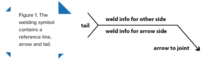
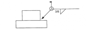
Welding symbols are drawn with a specific structure that describes the direction and type of weld to make.
Every welding symbol that you see will have an arrowhead which points to the location where you need to make the weld.
![]()
The arrow is connected to what we call a leader line.
This line intersects with additional reference lines that run horizontally.
The arrow can point upwards or downwards, signifying where to make the weld.
Finally, there is a tail at the opposite end of the reference line.
The tail may have several forks that point off in different directions.
This tail suggests specialized instructions for the weld.
If you look at the center of the reference line, you will see either parallel lines or a geometric shape.
These lines indicate the kind of weld you need to make on the metal frames.
There are more than a dozen types of welds that you can make. To do an accurate job, it is important not to confuse the weld symbols.
The symbols on the reference lines indicate the type of weld that should be done while the overall welding symbol gives you complete instructions for the welding project.
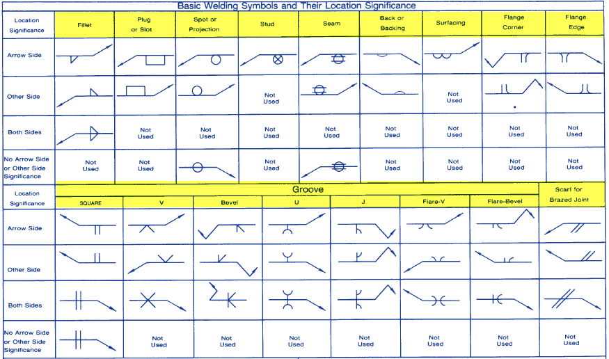
When you are reading a welding diagram, pay close attention to the placement of the symbol on the reference line.
If the weld symbol is present below the reference line, the weld should be carried out on the arrow side of the joint.
On the other hand, if the weld symbol is present on top of the reference line on the diagram, the weld should be made on the opposite side of the joint from where the arrow is pointing.
If the weld symbol is noted on both sides of the reference line, then multiple welds must be made on both sides of the joints.
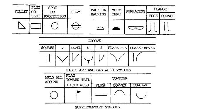
Various welding symbols have been developed to differentiate between the types of welds you can use on your project.
For example, a “||” shaped symbol indicates a square weld while a “V” indicates a V weld should be used.
Since there are so many symbols, it takes some time for welders to memorize the differences.
You can get a print out of the most basic symbols and put it on the welder to make it easier for you to recognize them.
Once you have memorized the most common symbols you can move on to additional symbols that aren’t very common.
Letters on the Welding Symbols
When you start reading welding blueprints, you will also find some letters on the charts.
These letters show you important information to consider when making the welds, such as length and root openings. Here is a reference to use for the letters.
- A: Angle of Countersink
- C: Chipping Finish
- F: Finish Symbol
- G: Grinding Finish
- L: Length of the Weld
- M: Machining Finish
- N: Number of spot welds or projection welds
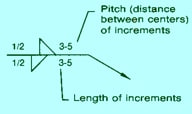
- P: Pitch of Welds (Center-to-Center Spacing)
- R: Root Opening; Depth of Filling
- S: Depth of Preparation; Size of Strength
- T: Specification Process
You will see these letters along with the symbols of welding if there is a specific weld that must be done to complete the project.
The letter may also be found on some welding blueprints on its own.
Dimensions and Angles
The welding symbol’s angles and dimensions are very important to note as they make it easier to understand the welding blueprint.
The blueprints are packed with information and provide a lot of information with just a few lines to an experienced user. They can be used to communicate length, width, depth and the opening of the weld.
The diameter or width of the weld is generally noted on the left of the weld symbol and will be written down as a fraction in inches.
The length, also expressed in inches, is written on the right of weld symbol.
Welding symbols also indicate whether the welds should be offset on both sides or mirror each other.
Welds are mirrored when they are made on the exact location of a sheet on opposite sides.
They are considered to offset one another when they are not made on the exact opposite location of the frame.
The welding symbol also includes the angle of the weld, its root opening or root face dimensions.
Numbers are a big part of identifying the weld depth and angle specifications. They help clarify the beveling required on the base metal before welding can be performed successfully above or below the reference line.
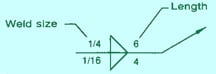
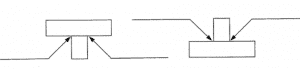
Dimensions written under the reference line are used for the joint on the arrow side while dimensions noted over the line apply to the joint on the opposite side.
If we look at the image above, welds are identified for both sides of the joint.
In some cases, a series of separate welds may be specified for a project that should be used instead of a single long weld.
When working with heat-sensitive or thin metals that can get damaged with a long and consistent weld, this is a common practice.
If you read the welding diagram shown below, you’ll see that a string of 3-inch intermittent fillet welds is recommended for the project:
If you ever see a flag at an intersection of the reference line do not perform the weld inside a workshop.
The flag is used to indicate that the weld must be carried out in the field.
Common Symbols and Their Meanings
There are dozens of cryptic symbols used in welding blueprints for identifying the weld.
These symbols help the welder understand the size and other finishing and processing information for the project.
In this section, we will go over some of the common symbols and their meaning.
You can find the complete set of symbols through the American National Standards Institute (ANSI) for welding.
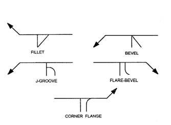
Fillet Welds
![]()
The fillet weld (pronounced “fill-it”) is generally used to make 90-degree lap joints, T-joints, and corner joints.
As the symbol shows, the weld is almost triangular at its cross-section.
The shape is not always a 90-degree right-angled triangle however and there can be some variation to the weld.
A small quantity of welding metal is deposited in the corner of the joint formed by the two members.
It penetrates and fuses with the material of the frames to form the joint.
The triangle’s perpendicular leg is always drawn to be on the left side of the symbol, irrespective of the orientation of the weld.
The size of the leg is written on the left side of the weld symbol.
If the two legs of the weld are supposed to be the same size, the symbol will show only one dimension.
If the weld is supposed to have legs that are different sizes then both dimensions will be given.
The drawing will also illustrate which leg is supposed to be longer.
Groove Welds
The groove weld is generally used to create joints that are connected between the edge of two different metal frames or sheets.
As can be seen by the image above, the groove weld can be made in a variety of ways.
This type of weld is also used in T joints, corner joints or joints between curved and flat pieces of metal.
The difference in welding mainly depends on the geometrical shapes of the parts that are to be joined together and how they are prepared at their edges.
During the welding process, the joining metal is deposited within the groove as it penetrates and fuses with the base metal on different sheets to form the joint.
The groove weld can be further classified into the following categories.
Square Groove Welds
This type of groove is formed by either creating a slight parting of the metal edges or a tight fit between two metal frames.
The diameter of the space created with this method, if any, is shown on the weld symbol.
V-Groove Welds
It is similar to the square weld with the difference being that the edges of both metal pieces are chamfered, on one side or both, to create the groove.
The degree of the V angle is present on the weld symbol, as well as the separation at the root, where required.
In case the groove is created by separating the metal, the thickness of the groove may not run fully deep into the metal sheet.
Bevel Groove Welds
In this type of weld, the edge on one side of the joint is chamfered and the other edge is left square to create a bevel groove.
The bevel symbol’s perpendicular line is always drawn on the left side irrespective of which direction the weld is oriented towards.
The arrow points toward the metal joint that must be chamfered. The significance of the direction is emphasized by breaking the arrow line.
U-Groove Welds
This weld is formed by giving a concave treatment to the edges of both metal pieces. When joined together, they form a U-shaped groove.
Depth of this edge treatment, separation at the root and effective throat are shown by using the same method as the V-groove.
J-Groove Welds
The J-groove is formed by giving a concave treatment to one piece of metal and leaving the other one as a square.
This is done in a process that is similar to the bevel groove joint formation.
The perpendicular line is drawn on the left and the arrow points to the metal that receives the concave edge treatment.
Depth of edge treatment, root separation, and effective throat are described in the manner shown below.
Flare Groove Welds
This type of weld is used to join two or more rounded parts together. The ideal depth of the weld is shown on the left side of the symbol while the weld depth appears in parentheses.
Plug and Slot Welds
![]()
Plug welds and slot welds are used to join frames and metal sheets that overlap one another. Usually, both the pieces have holes in them for connecting them.
Metal sheets with plugs have round holes while elongated holes are built into slot sheets.
Weld metal is deposited inside the holes as it penetrates and fuses with the base metal of the two sheets to form the joint.
For plug welds, the diameter of each plug is given to the left of the symbol. The pitch of the plugs is labeled on the right.
In slot welds, width is used for each slot which is given on the left side of the symbol while the length and pitch are illustrated to the right of the symbol. The detailed drawing is referenced near the tail.
The total number of plugs or slots to weld is given below the weld symbol in parenthesis. The arrow side and other side designate which piece contains the hole(s).
In a case where the hole does not need to be filled completely with welding metal, the depth for filling it up is noted within the weld symbol.
Putting It All Together
Some of the welding diagrams shown above have the metals represented as two blocks coming together.
This is done to make it easier to understand how the weld should be performed. This is usually not the case for an actual welding blueprint.
A real welding diagram looks more like this.
In some welding blueprints, you will also see the reference lines with a break.
This indicates that preparation should be done for the joint, before welding the pieces together.
The design of the break also represents the kind of preparation that should be done for the weld.
If you are just starting out with welding blueprints, you may find it difficult to read and understand how the blueprints work.
Sometimes, the drawings are too complicated and confusing, even for experts. It takes time and patience to learn how to read them.
Once you master the art of reading blueprints, it will become easier and you will be able to create beautiful and advanced projects without trouble.